
Model Description
This simple pair of K’NEX models can demonstrate how trusses greatly increase the strength/stiffness of structures without adding much weight. The trusses are built out of K’NEX pieces and topped with construction paper to produce a roadway. Text books are used to load the trusses to demonstrate its strength to weight ratio. This demonstration should take 15 minutes.
Engineering Principle
The basic equations required for analysis are the equations of equilibrium and trigonometry. However, no real numerical analysis is required beyond measuring the weight. The model is used primarily for developing a feel for the importance of trusses as a structure, especially when considering the structure weight to load carried ratio, and that the weight of the truss can be initially ignored during the design (add weight of truss members back in during the final design checks).
What You Need
| Item | Quantity | Description/Clarification |
|---|---|---|
| K’NEX Pieces | Lots! | These pieces are connected into a number of triangle shapes to form 2D and then 3D trusses with supports. The connection of the 2D trusses forms a rudimentary “road” for the bridge. Also, a so-called “road” without trusses is made to demonstrate how flexible a bridge can be without trusses (long members overly dramatized for effect). All of the K’NEX pieces shown are part to the Big Ball Factory set. Individual pieces can be purchased to build your own kit. For the bridges in Figures 1, 2, and 3, you will need: Bridge without trusses – 7 yellow (3.25 inches) straight pieces, 12 blue (2.125 inches) straight pieces, 28 purple connectors (2 each forming a joint); Bridge with trusses – 17 yellow (3.25 inches) straight pieces, 30 blue (2.125 inches) straight pieces, 2 red (5.125 inches) straight pieces, 4 white (1.25 inches) straight pieces, 20 purple connectors (2 each forming a joint), 4 green connectors, 14 yellow connectors (2 each forming 4 supports), 2 red connectors. |
| Load (textbooks) | Any | Test how many textbooks is safe for the K’NEX truss model so as to not actually break the connections, but make sure the number of books is effective in making a point about the strength of the bridge. |
| Construction Paper | 2 | Two pieces of construction paper make the roads for the two bridges. |
| Tape | 1 | Tape is used to attach the paper to the two bridges. |
| Supports | 2 | Supports are needed to hold the ends of the bridges off of the desk while they are being loaded. Anything can be used for this: more textbooks for example. |
| Scale | 1 | A scale is used to weigh the truss and the load it is able to carry successfully. No scale is really required. A student can provide a qualitative answer by placing the truss in one hand and the load carried in the other hand. |
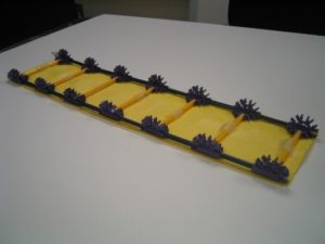
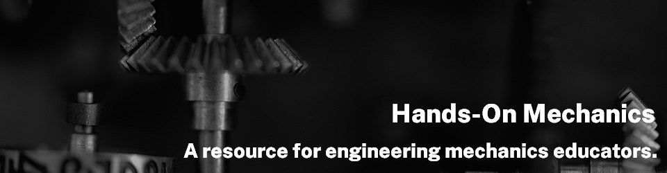
Figure 1: Bridge model 1, underside.
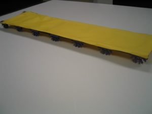
Figure 2: Bridge model 1, topside.
Figure 3: Bridge model 2, underside.
How It’s Done
Before Class: Construct the bridges out of K’NEX and load test the truss bridge to make sure you don’t overload it and break it during class (normally only connections come apart, but occasionally, the textbooks can cause a connector to occasionally break a small piece off), especially if teaching multiple sections of the same lesson.
In Class: Show the class the bridge without trusses. Place it in the hands of a student and ask how much it weighs (qualitatively). Place it on the supports and place a light object on it and show how it begins to deflect under the load. Ask the student to compare the weight of the structure and the load placed on it (qualitatively). Show the students that it is bending and ask why it isn’t very strong. Generally long slender members acting as simply supported members are not efficient in supporting loads over long spans. How can we make the structure stronger – greater depth to the members (Draw on their experience of building a tree house using 2×4 members. The member is stronger when loaded perpendicular to the greatest depth – use a ruler to demonstrate)? How can we get greater depth without too much more weight? If and when you can elicit a statement about trusses from the class, bring out the other bridge.
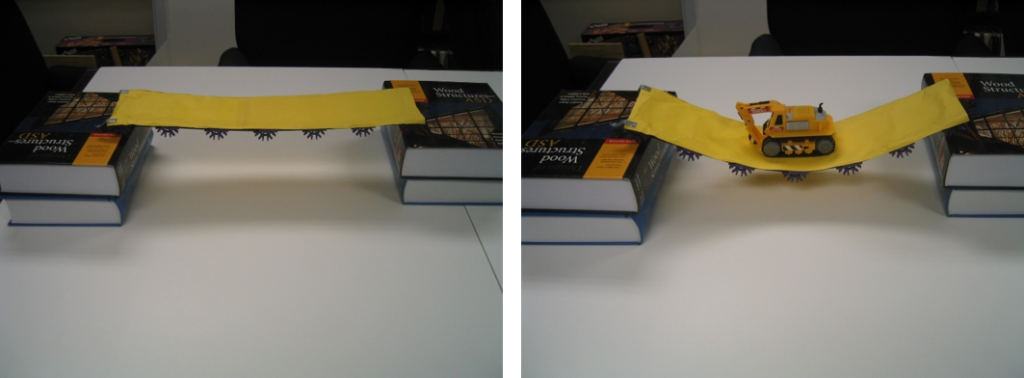
Figure 4: K’NEX bridge model 1 supported (left) and loaded (right).
Ask the same student how much it weighs compared to the first non-truss bridge (not much more…). Set the bridge with trusses on the supports and place the same small object on it. Lead the class to see how much more load it can support. Begin to load textbooks on the bridge (can use some of the students’ texts).
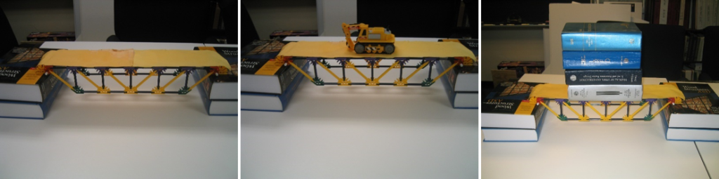
Figure 5: K’NEX bridge model 2 supported (left), lightly loaded (middle), and heavily loaded (right).
Weight the bridge, then the textbooks. There should be quite a significant difference in ratio between the weights. A light truss structure can support a load that is many times greater than the weight of the actual structural members over long spans.
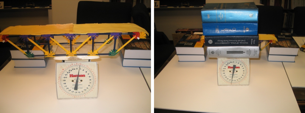
Figure 6: Using a scale to weight the bridge (left) and the textbooks (right).
Additional Application: Before loading the truss bridge, ask a student how much it weighs by placing the bridge into his/her hand. Then ask how much load the bridge might be able to support? Once the students see how much stronger the bridge with trusses is as compared to the one without trusses, call one of the students up to the front of the class. Give the student the two bridges to hold and ask if there is much significant difference in weight. Then take away the bridge without trusses and begin to stack the textbooks that had been loaded on the second bridge onto the student’s hand until all are there of he/she cannot hold any more (drama and fun!). Then bring out a scale to show numerically how different the weight of the bridge is when compared to the weight of the load.
More elaborate truss structures/supports that represent real bridges can be developed for this same demonstration. This bridge is an approximate example of the Falls Bridge over the Schuylkill River Philadelphia, PA (Figure 7, left).
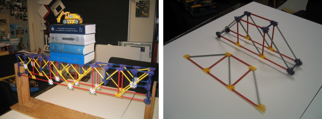
Figure 7: An approximate example of the Falls Bridge over the Schuylkill River Philadelphia, PA (left) and a 2D truss section (right).
Building a 2D K’NEX section (see Figure 7, right) of a 3D K’NEX truss allows for a discussion of actual analysis of 3D structures. The 3D bridge structure is mentally taken apart into two 2D sections with one-half of the deck load (for this case) placed on each half. The engineer then draws a Free Body diagram (FBD) of the 2D section and completes the analysis to determine the loads in each member. This K’NEX model matches the planned in class truss analysis problem using both the Method of Joints and Method of Sections.
A discussion can ensue concerning other portions/assumptions of the definition of a truss: a structure composed of slender members joined together at end points by frictionless pins; loads only applied at joints; all truss members are 2-force members; and member weight is negligible. Slender members is obvious, but showing connections using K’NEX pieces leads to discussion/review of a previous topic – concurrent force systems and frictionless pins of years gone by. The fact that truss members are 2-force members will be shown during analysis using Method of Joints and Sections. The load (books) not totally going through the joints leads to a possible discussion that truss members are not always only 2-force members (if the class has been prompted to know the difference between the current theory and what real structures experience and adjustments to analysis at later times). Usually, the deck will carry the load to the joints. Member weight is generally negligible – readily apparent by the initial demonstration.