

Overview
Thrill your students with Tales of Torque using the versatile Tower of Torque! In it’s simplest form, the device allows students to predict and then measure the capacity of a simple bolt, modeled as a rod in torsion.
Principle
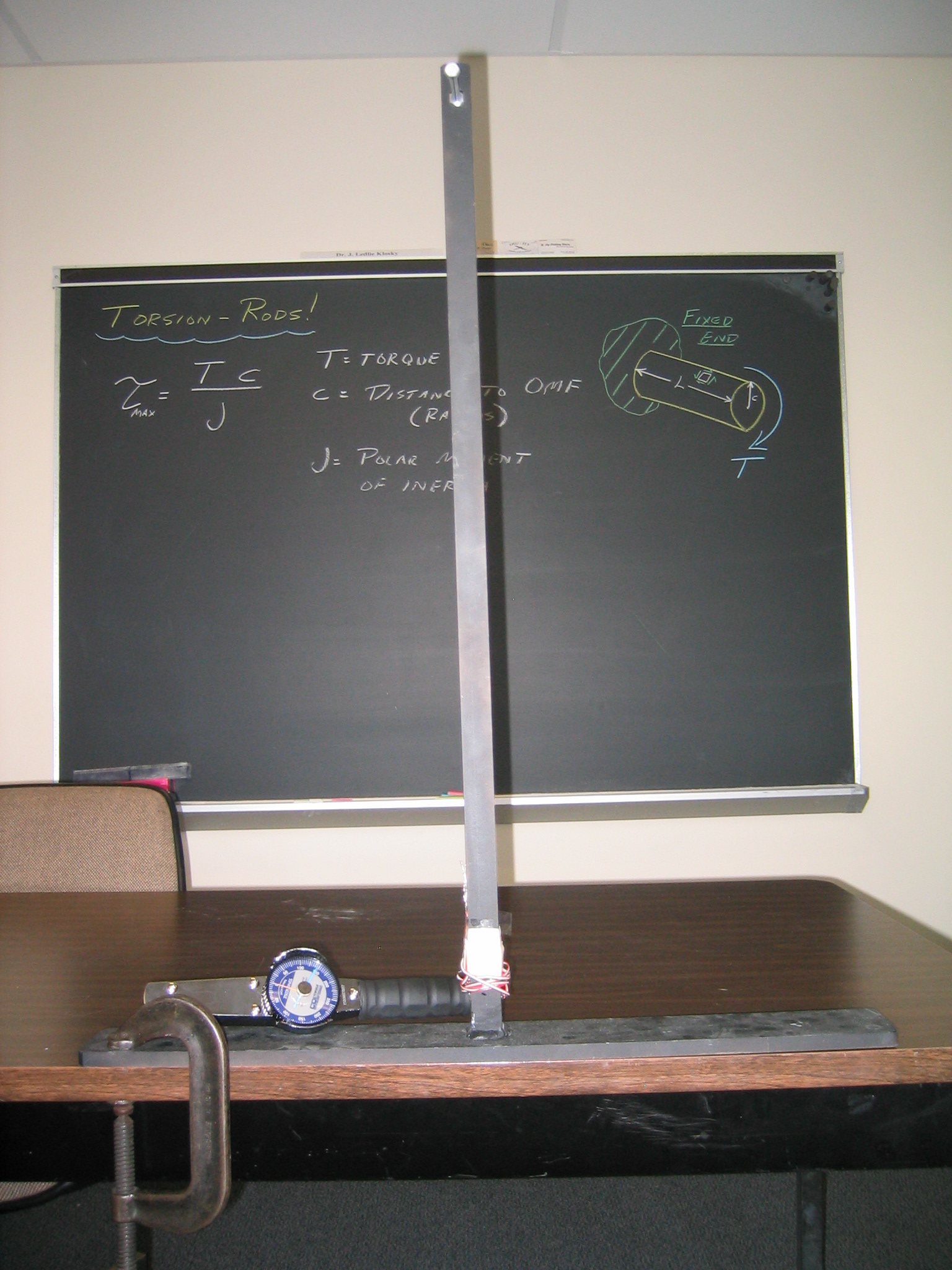
For cylindrical rods in torsion, the maximum shear stress experienced is seen at the outer surface, and for materials in the elastic range the shear stress is computed using the expression

where the shear stress 
What You Need
| Item | Quantity | Description/Clarification |
|---|---|---|
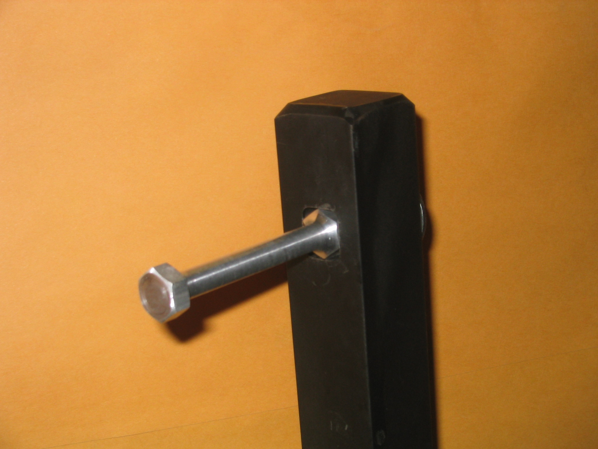
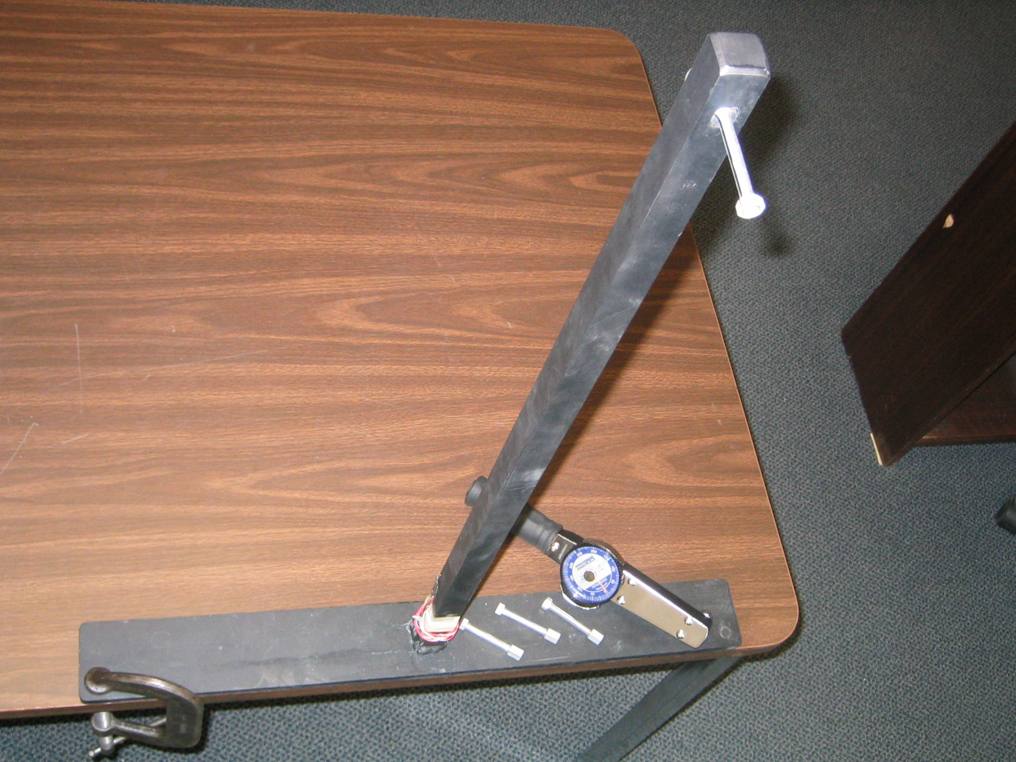
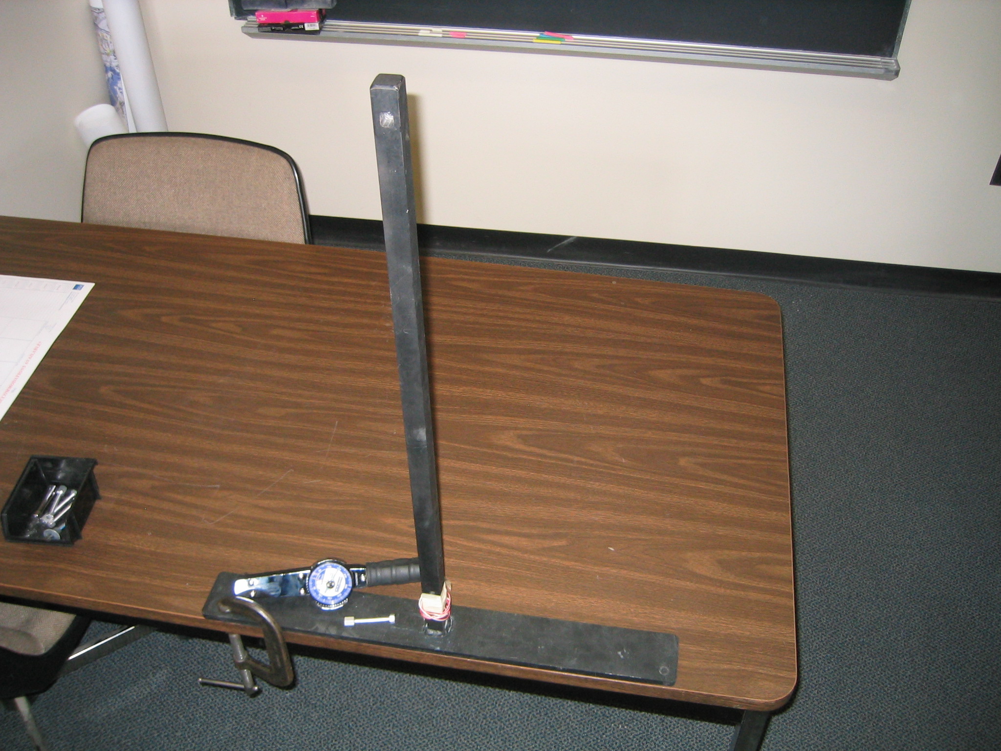
| A Tower of Torque | 1 | A steel base plate with a 1-inch-square steel “mast” projecting from the base. The top of the mast is capable of receiving a real or simulated bolt. Complete plans are here. |
| Torque Wrench | 1 | The torque wrench should have a large dial, and the failure torque for the chosen sample should be roughly half the total range of the wrench. It only helps a little if the wrench has a maximum value indicator (a follower). |
| Torsion Samples | Various | Samples consist of 1/2″ aluminum or other hex stock turned down to a quarter of an inch in the shank. The samples should be tested thoroughly and a proposed configuration , though certainly not the only one possible, can be seen on page two of Sample Detail Drawings. |
How It’s Done
Building the Demonstrator: The demonstrator is actually fairly straightforward, and measurements/etc can be seen in the plans. The device basically consists of a steel baseplate normal to which a 1″ square steel mast is attached by welding. Near the peak of the mast, at a recommended distance of 30″ above the base, a square hole is milled to accept the torsion samples. Don’t worry too much about making the milled hole exactly square, as the sample will not make contact with the corners of the square since it is a hex. If you like, you can leave the milled hole closed at the back to facilitate keeping the samples positioned right.
The Samples: Details of the samples we use can be found at Sample Detail Drawings. The key property of the samples is that the shafts must be turned down to the point that they can be readily failed in torsion using something like half the total available capacity of the wrench you choose. Practice, practice, practice! Sample strength varies even within the same hex rod, so make sure that the sample will do what you want it to do when the money is down. We also mark the samples with a line along the shaft (use a Sharpie to do this easily) so that the permanent set in the samples due to yielding can be directly observed by students.
Before Class: Secure the base of the demonstrator to a desk or workbench somewhere in the classroom where it will be highly visible to all the students. To save time and raise curiosity, mount the sample in the demonstrator prior to the beginning of class. Check out the direction of the torque wrench to make sure that you rotate it the right way when the moment comes, as not all torque wrenches are bi-directional. Make sure to test the whole apparatus at least once prior to use. There’s nothing worse than demonstrating that theory has no bearing on reality…!
In Class: If you’d like, you can view a complete video of a run-through of the demonstration by clicking on the demonstrations at the top of this page. Basically, the procedure can be broken into the following steps:
- If time is plentiful, ask the students what they think about the demonstrator, and see if they can guess what the demonstration is.
- Have the students compute the minimum applied torque required to cause yielding of the sample. Dig into the fact that the measured torque will likely be higher than the minimum computed value and why. Consider discussing 95% confidence limits if time is available.
- Slowly apply torque to the sample, having a student call out values as they increase. Try to observe the onset of yielding, and show the students the deformed line on the bolt indicating permanent (non-elastic) deformation.
- After observing yielding, continue to twist the bolt all the way until failure.
- Show/pass around the failed part, and discuss what they just saw.
Be careful not to try to measure the angle of twist using the torque wrench handle, as the angle through which the handle moves is larger than the that of the bolt (there’s a spring in the wrench for measuring the torque!). Further, holding the point of contact of the bolt and wrench steady with your hand helps lower the effects of the combined load on the sample.
Observations: Students should observe that the basic equation for torsion allows for a good estimate of the actual torque necessary to fail a bolt with a wrench. They should also observe that permanent deformation can take place in thin parts through the application of very little torque.
Extra Example
More fun and drama can be added to this class by adding the “Helicopter Mechanics” scenario. Basically, you describe a scenario in which a helicopter maintenance person feels it is necessary to get an aluminum bolt “good and tight”. Then, while turning the sample with the wrench at or over the predicted failure torque, say to the class “It must really be getting tight and strong now !”. They will realize that tightening the bolt further will really just weaken it, causing the fiery death of the very pilot the mechanics was trying to protect. Lessons on that little extra in this case includes ‘Knowledge is power’.