
Model Description
This is a simple demonstration to introduce the basic principles of experimentation, analysis, and design in reference to axially loaded members. Copper wire is used to lift an object of known weight. In order to determine the minimum number of copper wire strands required to lift the load, students perform experiments, analysis, and design calculations. The discussions in class inherently lead to an understanding of the practicality of experimentation, the need for a factor of safety in actual design, and actual-versus-allowable stress. This demonstration should take 15-20 minutes.
Engineering Principle
The basic equations for axially loaded members:

where

and

therefore,

where the actual normal stress imposed on the member must be lower than the allowable normal stress. The actual normal stress in a member is the axial load over the cross sectional area. The allowable normal stress in this case is the ultimate strength of the material divided by a factor of safety. Therefore, if the material properties, expected load, and factor of safety are all known, the required cross sectional area can be determined and the member can be sized to carry the load.
What You Need
| Item | Quantity | Description/Clarification |
|---|---|---|
| Copper Wire | lots | Any wire will work, but the ultimate strength and diameter must be known before class. Copper wire is preferred as it ruptures without having to use much weight. The wire used in this example is annealed copper wire with a diameter of 0.006 in., a yield strength of 8,000 psi, and an ultimate strength of 33,000 psi. |
| Load | 1 | Use anything as a load. This demo uses a load with a total of 5 lbs. |
| Scale | 1 | Any scale to determine the weight of the object. |
| Crane2 | 1 | The easiest objects to use as your crane are yard sticks or broom handles. Depending on the level of drama you want in the classroom, you can enhance your crane by using more complicated setups as seen in the photos below. |
How It’s Done
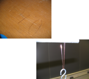
Before Class: Prepare several loops of copper wire with various numbers of strands (figure below, top). Prepare the load you are going to lift by ensuring that it has something (like a hook) (figure below, bottom) to attach the loops of copper wire. It is important that you make a couple of trial runs before class to ensure that secondary effects (like kinking of the wire) are minimized and don’t drive the behavior.
In Class: Challenge the class by asking them to determine how many strands of copper wire are required to lift the given load. Weigh the load in front of the class and record it on the board. (In this example, the load is 5 lbs.)
Conduct the experiment portion of the lesson. Ask the students if one loop (two strands) of copper wire will carry the load. Try to lift the load with two strands of copper wire. Given the example 5 lb load and copper material properties described above, the copper fails with two strands. Ask the class what they suggest. Inherently the students will suggest adding more wire. Try to lift the load with your pre-made loop of four strands. In our example the wire deforms more slowly than before, but still ruptures. Discuss with the students that experimentation is great in the classroom and a lab, but is not feasible on a real job site. This will lead into the need for design.
Conduct the design portion of the lesson. Using the equations described above, rearrange and solve for the minimum cross sectional area required to lift the load.

In our example:
P = 5 lbs.
F.S. = 1 since we merely want to lift the load

Solving the equation:
A ≥ 0.000152 in2
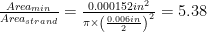
Dividing this value by the cross sectional area of one wire with diameter of 0.006 inches will yield the minimum number of wires required to carry the load:
# of strands =
Therefore, based on design, we will use 6 strands to ensure that the wire does not break. Conduct another experiment using 6 strands. You will be able to lift the load. Now ask the class how confident they are with 6 strands. Tell them in real life there might be some circumstances that require more strands; it might be a windy day, the crane operator might not be smooth on the controls, the load may be slightly higher than we estimated, etc. At this point shake the crane rig slightly and it should fail.
Now is the best time to introduce the importance of factor of safety and how risk comes into play. Perform an analysis using 8 strands and determine the factor of safety you are building into the design. Rearranging the equation and solving for F.S.:

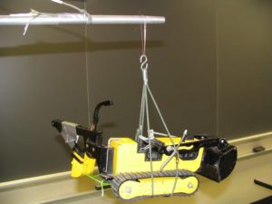
Additional Application: As you can see, you can use toy tanks, cars, or anything as a load to grab the students’ attention. Your crane setup can be extravagant; in the video we have a system of pulleys and we’ve also used toy cranes. During the experiment portion of the lesson students will start to enjoy the lifting of the tank, and the subsequent breaking of copper wires. Tell the students when they start testing that they are responsible if anything breaks! This will bring home the point that if you are to lower your risk, you need to increase your factor of safety. However, increasing your factor of safety will increase your cost too. With some basic role-playing (the instructor is the contractor and the students are the engineers) you can get the students to realize that the number of wires chosen can impact a career!