Model Description
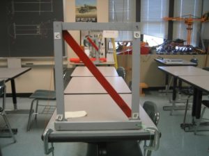
This is a simple model that will demonstrate the use of zero force members (ZFM) in trusses. Wooden beams are attached with dowels to form a simple truss, which is acted on by an external force. The zero force members are identified by placing a load on a truss and then removing pins at the joints to see if the truss is affected. This demonstration should take 15-20 minutes.
Engineering Principle
The basic equations for equilibrium of a truss joint (Method of Joints) are:

where the sum of the forces in both the x and y directions are equal to zero.
What You Need
| Item | Quantity | Description/Clarification |
|---|---|---|
|
Wooden members |
5 |
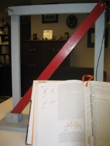
The vertical members (gray) are 21 in. long. The horizontal members (gray) are 16.5 in. long. The diagonal member (red) is 25.5 in. long. Each member is about 0.75 inch thick and 1.5 inches wide. Each member has a slightly larger than 0.25 inch hole drilled in each end to connect them with 0.25 inch dowels (dowel should slide easily). One of the vertical members has a hook at the level of the connection hole and one of the horizontal members has a hook at one end. |
| Base | 1 |
The base is 20 inches long x 6 inches wide x and 5/8 to 3/4 inch thick. The base is used to clamp the ZFM demonstrator to a heavy desk. 4x 1.5 inch tall x 2.25 inch long x 0.75 inch thick pieces nailed to the base provide the supports for the vertical and diagonal members. |
| Dowels | 4 |
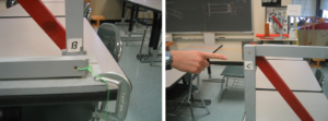
The 4 inch x 1/4 inch dowels will act as pins to hold the members in place. |
| Clamps | 2 |
Clamps are necessary to hold the truss to the heavy desk/table. |
|
Load (student) |
1 |
The horizontal load applied to the truss will be applied by a student pulling on a string attached to a hook. |
| Hooks | 2 |
The eye hooks are positioned on either side of the truss on vertical and horizontal members where horizontal load will be applied. |
| Pliers | 1 |
Any set of pliers will do. |
| String | 1 |
A moderately strong string is necessary to apply a load to the side of the truss. |
How It’s Done
Before Class: Prepare the wooden truss for class and check with test loads to see that it can support a student without risk. Make sure the dowels are in place properly and won’t break.
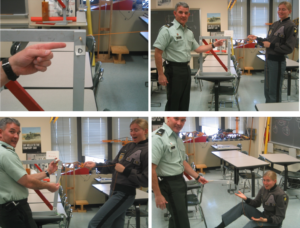
In Class: Ask for a student volunteer to be the load through the string attached to the hook (on the vertical member) on the joint of the truss where three members intersect (Joint C). Have her lean back and close her eyes (drama!). Ask the class what they think would happen if you pulled out any dowel. The dowel at Joint D? You can possibly lead the students to see that the load will flow through the horizontal member to joint D and then down the vertical member (not true, but sets up the drama and the learning point). Hopefully the students will conclude that the student inducing the load will fall down when the pin is pulled. At this point, you may have to work on getting the student to keep her eyes closed. Tell her to trust you since you work for the government (university). Tell her you are about to pull out one of the dowels and to let you know if she feels you pulling it out with pliers. You should be able to pull out the dowel at joint D easily since there is no load in members BD and CD. After a few seconds of continuous talking and with the dowel out and the members dangling (lower by hand so the student cannot feel the movement), tell her to open her eyes with you holding the dowel for everyone to see. Ask her to take her seat and address the whole class about why removing one of the dowels had no effect on the way the truss worked. Work through with the Method of Joints at Joint D and mathematically demonstrate that both members are ZFMs.

This example (focusing on joint D) demonstrates a general rule about zero-force members: if there are two members connected at a joint, and the members are non-collinear, and no external load is applied at this joint, then both of these members must be zero force members.


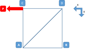
Another general rule about zero-force members is as follows; if three members connect at a joint, two are collinear and the third is non-collinear, and no load is applied at the joint, then the non-collinear member is a zero-force member.
Additional Application: A question should be raised about why these zero-force members are put into trusses. Call a student to the front of the class to demonstrate what happens when you move the load to Joint D. Move the string from Joint C (hook on the vertical member) to the opposite side of the truss at Joint D (hook on the horizontal member) and have the student pull on the string once more. Ask her to lean back and shut her eyes – which she will probably do more quickly as the trust has been developed. Try to remove the dowel, and show that its removal would require much effort. Tell the student to sit down before she hurts herself (with the hook on the horizontal member, she will not fall down since the horizontal member is still connected at Joint C). Work through with the Method of Joints at Joint D to explain that the member that was zero-force member (horizontal member) under one condition is no longer a zero-force member under this new condition. The reason for ZFMs is that the load may move to another joint and ZFMs may be required to support the load at the new location. Sometimes ZFMs are used to support members in compression with the ZFM connected at the mid-point of the member in compression. Shortening the length of the unsupported section can actually strengthen the compression member by a factor of 4. This can be demonstrated using a wacky fun noodle – see Wacky Fun Noodle demonstration.
If you really want to pull the pin at D with the student creating a horizontal load, the hooks can be screwed into the end of the horizontal member instead. When the pin at D is pulled, the student is still supported by the horizontal member that is still connected to the stable triangular truss structure at Joint C.