
Model Description
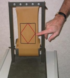
A thin rectangular sheet of rubber material is subject to an axial load. Stress blocks are painted or drawn on the rubber material. The stress blocks are oriented on a transverse plane (black square) and on a plane 45° from the transverse plane (red square). Students have previously learned that only normal stress exists on the transverse plane and the 45° plane experiences the maximum shear stress. As the rubber material is stretched, the students can see that sides on the transverse stress block get longer in the longitudinal direction and shorter in the lateral direction while the angles at the corners do not change. Students can use a ruler to compute the normal strain and Poisson’s ratio for the material. Similarly, on the 45° stress block, the lengths of all four sides increase the same amount and the angles change. The angles on the top and bottom corners get smaller and the angles on the left and right corners get larger. This demonstrates that shear stresses and strains exist within an object subjected to an axial load.. This demonstration should take 35 minutes.
Engineering Principle
Normal strain in the longitudinal direction (


Conversely, the width of the stress block is getting smaller. The strain in the lateral direction (


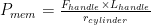
Poisson’s ratio (

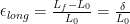
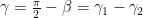
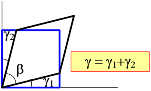
The shear strain (
For an axially loaded member, the shear stress and the normal stress are different for different planes.
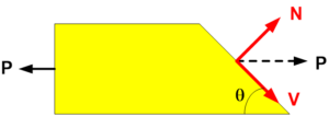
For any given angle (


Similarly, the Shear Modulus (G) of the material relates the shear stress to the shear strain, 

What You Need
| Item | Quantity | Description/Clarification |
|---|---|---|
| Thin sheet of rubber material | 1 | A thin sheet (1/16”) of rubberized material. Approximate dimensions should be 18” long by 5-1/2” wide. Use permanent markers to draw a 4-3/16” square transverse stress block. Inscribe a 45° 3” square stress block inside the transverse block. |
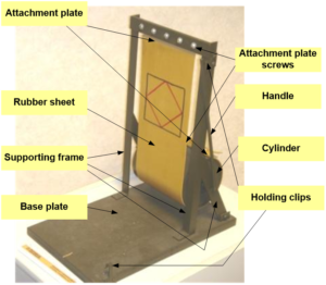
| Steel frame | 1 | The rubber is supported by a steel frame consisting of two vertical members (16” long), a top horizontal member (8-1/2” long) and two supporting braces (8” long) . The vertical members are 3/4” by 3/4” by 1/8” angle pieces. The top horizontal member and the braces are 1” by 1/8” plates. The frame members can be connected by welds or small bolts. The frame is connected to the wooden base using screws. |
| Wooden base | 1 | A 15” by 9” piece of 3/4” thick wood is used as a base for the device. |
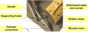
| Cylinder | 1 | A 4-1/2” diameter cylinder is used to hold the bottom of the rubber sheet. The cylinder is supported by the frame and is free to rotate. The cylinder device shown here is made of wood, but a coffee can has been used on previous devices. |
| Attachment plates and hardware | 1 | The rubber sheet is attached to the top of the structural frame and to the rotating cylinder at the bottom. The rubber sheet should be wrapped around a 1/8” supporting plate (5-1/2” by 1”). Without the plate, the rubber will rip through the supporting screws when a load is applied. Screws or bolts should be used to attach the plates to the steel frame on the top and the cylinder on the bottom. |
| Handle | 1 | A 1/4” diameter handle is attached to the center of the cylinder and bent at a 90° to rest at the top of the steel frame. The length of the handle is 12” measured from the center of the cylinder. The load is applied to the rubber material using the handle. The user pulls on the handle which causes the cylinder to rotate which in turn stretches the rubber membrane. Photos below offers a better view of the handle/cylinder connection. |
| Holding Clips | Any | The handle is secured in the unloaded and loaded configuration using holding clips as shown in the photo. One holding clip is attached to the top of the supporting frame and one is attached to the wooden base using screws. |
The total cost should be in the range of $50 to $75 and the build time is 2-3 hours.
How It’s Done
Before Class: Bring the axial strain device, a ruler and a protractor to the classroom.
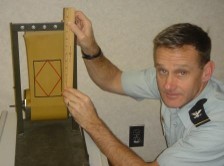
In Class: Measure the lengths of the undeformed stress blocks with a ruler and record the results on the board (figure below). Verify with the protractor that the angles on the corners of the stress blocks are 90°. Pull on the handle which rotates the cylinder and stretches the rubber membrane. Lock the handle into the holding clip in the wooden base. Measure the new lengths of the deformed stress blocks and use the protractor to record the angles at the corners of the stress blocks.
For a short demonstration, the students will be able to see the qualitative difference in the two stress blocks as they change from the undeformed to the deformed position. Getting the students to describe what they see and attempting to relate this to stress-strain theory is an effective 2 minute learning demonstration. For a more detailed demonstration, make some computations based on the measurements and assess whether they support the theory. For the device shown in the photo, the measured results and sample calculations are shown below:

Initial data measurements:


Note that the transverse normal stress should be about double the normal stress on the 45° plane. Similarly, the normal stress and shear stress on the 45° plane should be equal. Given the precision of the measuring instruments used (ruler and protractor), these results are not bad.
Additional Application: Rather than looking in a reference book for the Young’s Modulus value for rubber, you could use this device to compute the approximate value. You have already computed the longitudinal strain value when the handle is in the extended position. Attach the handle to a spring loaded scale (similar to those used to weigh a caught fish). Determine how much force it takes to hold the handle in the extended position. Compute the force on the rubber membrane (


The normal stress on a transverse plane is 
