Model Description
These physical models easily and quickly demonstrate the behavior of varying cross-sectional shapes to varying loading conditions. When the instructor passes the rubber shapes around during class, students personally experience the associated behavior and quickly catalog for themselves when shapes are best used. Applying vertical, horizontal, and circumferential lines along the length allow for physical representation of the assumptions associated with each type of loading and shape that are not always intuitively obvious to our students. This demonstration should take 20-25 minutes.
Engineering Principle
The shape of structural members affects their behavior during loading. Some shapes have more strength and stability versus other shapes when identical forces are applied. Flexural, axial, torsional, and buckling behaviors and assumptions can be demonstrated and experienced using these rubber shapes. Additionally, the importance of a shapes area moment of inertia (a physical property) can be highlighted.
What You Need
| Item | Quantity | Description/Clarification |
|---|---|---|
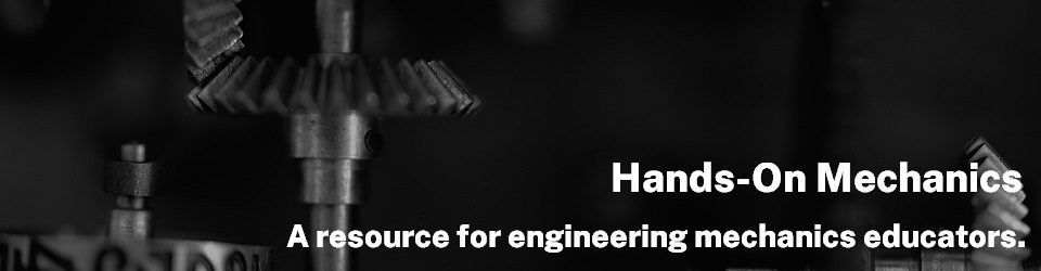
| Rubber Cylinders | 2 | These are about a foot long and an inch in diameter. To demonstrate torsional behavior of cylindrical members, draw 10-12 lines lengthwise and evenly spaced around the circumference of the cylinder. These lines should form squares. On the other cylinder, you can draw one large square. |
| Rubber Rectangular Members | 2 | Dimensions are 12” long x 1½” wide x ½” thick. Various patterns can be drawn on the largest side of one of the members to demonstrate flexural behavior. Generally vertical and horizontal lines along the length are drawn. |
| Rubber Wide-Flange Beams | 2 | Dimensions are 18” long x 2” tall x 1½” wide (flange) and ⅛” thick (flange and web). |
| Rubber Angles | 2 | Dimensions are 18” long x 1½” x 1½” (⅛” thick) – an equal leg angle. When two angles are clipped together, we can demonstrate the need for intermediate connections along the length in order to increase the strength (due to buckling). |
| Binder Clips | 3 | These are used to hold the two angles together. |
How It’s Done
Before Class: Draw the patterns on the shapes that require it based on the lesson at hand. Be sure you have all of the shapes and clips necessary for each demonstration.
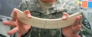
In Class: Depending on the lesson, bring out the rubber shapes of choice for everyone to see. If the lesson is on torsion, maybe both the rectangular and cylindrical shapes are used. Ask the students: how the different shapes will behave when applying a torsional moment? First, take the rectangular beam and twist is and see that it warps. Twist the cylinder and notice that it does not warp and is possibly a more efficient shape for members that will experience only axial loads and/or torsional moments. Start with the rod with only a single square drawn on it. Ask the students: what will happen to the square if the rod is twisted? Twist the cylinder with a single square drawn on it. Show the students how the square turns into a rhombus (figure below). The area of the square does not get larger, but the square just changes shape to a rhombus. This behavior opens the discussion on the pure shear behavior of cylindrical shapes and can be demonstrated numerous times during the development of the shear strain/stress theory.
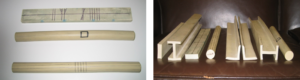
The discussion can be further enhanced with the twisting of the other rod with the series of lines along the length and around the circumference (figure below, left). Highlight that the longitudinal lines twist like a candy cane while the vertical lines do not distort – stay vertical (figure below, right). The squares still deform to form a rhombus where the square changes shape, but not size. This demonstration depicts key highlights of pure shear deformation. Additionally, highlight how the overall shape of the rod does not change when twisted in comparison to the rectangular beam. The rectangular beam can be twisted to show warping.

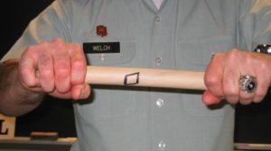
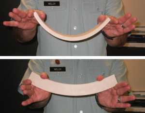
During lessons on flexure, use the unmarked rectangular beam. Ask the class which way it would hold more load? Apply a moment to the beam when it resists with the smallest area moment of inertia (figure below, top) and observe how easy it is to bend and how much it bends. Rotate the beam and apply a moment when it has the largest area moment of inertia (figure below, bottom) and note how much more difficult it is to bend it and how little it bends. Most students can make this connection to their experiences of using left over 2”x4” wood members to build a fort, a tree house or a foot bridge over a neighborhood stream.
Just as with the foam beam example, vertical and horizontal lines drawn along the length demonstrate the assumptions associated with flexural behavior. Point out the deformation of the horizontal lines—they are now curved—but the central horizontal line did not change in length while the top and bottom lines did change length. This can also be seen by observing the change in the space between the vertical lines. At the top of the beam, the lines moved closer together (compression), while at the bottom of the beam the lines moved farther apart (tension). You can also point out that the spacing between black lines does not change along the neutral axis. But also point out that the vertical lines themselves did not deform – they are still straight, unless we load the beam to cause large deformations… This is similar to what can be shown using the foam beams.
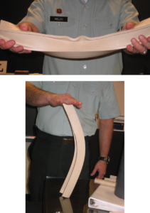
The wide-flange shaped beam can demonstrate the additional stiffness when the area moment of inertia is increased by moving more of the cross-sectional areas further from the shapes neutral surface/axis. The shape is very useful in steel design when desiring to demonstrate lateral-torsional buckling of wide-flange members (if not discussed in Mechanics of Materials). When moments are applied to either end of the long beam, it experiences lateral-torsional buckling and buckles laterally. But as the length of the beam between load points is decreased, greater moments are required to cause lateral-torsional buckling (figure below, top). So the importance of intermediate lateral support is directly shown and physically demonstrated/emphasized for the students. Additionally, wide-flange members are used as columns. Again, with no intermediate supports along the length, a longitudinal load will result in the column bending/bucking about the weak axis or the axis with the smaller area moment of inertia. Point out the fact that when a wide-flange member is used as a beam or column for its greater flexural strength along one of the axis, the weaker axis generally requires some type of lateral support (figure below, bottom).
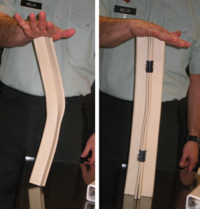
The final rubber shape member is the angle. When an axial compressive force is applied to a single member, it buckles easily (figure below, left). So usually we see the use of this shape for tension bracing members. Ask the class: what they think would be best to modification to address the issue of buckling? Hopefully the previous lessons will have highlighted the need for additional area moment of inertia. Use a second angle and clip them together using the binder clips – one at each end. Apply the same force to the new composite member in the same method as before and demonstrate that the column doesn’t buckle as easily, but it might still buckle some at the center. Add another clip in the center, and reapply the load to demonstrate that even more load is required to buckle the double angle configuration (this step might not be required if not applying to large of a load and if you are going to demonstrate the next step below in the same class) (figure below, right). Again, the importance of area moment of inertia is highlighted, but also the importance of connection of multiple members to ensure that the individual members must be made to act as one to gain the desired advantage – increased (buckling) strength.
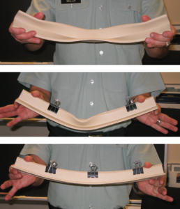
The same general behavior can be demonstrated while loading an angle in flexure. Once again, it buckles while demonstrating lateral-torsional buckling at mid-span (figure below, top). Ask the class again what should be done. It is now clear that additional area moment of inertia is required (another angle) and that the angles must be connected. Once the class gives the answer, clip the two angles together with two clips just as before (figure below, middle). Apply the same moment to the ends of the beam so that it buckles in the middle. Once again, ask the class what should be done. Attach a third clip to the middle of the beam and show that this beam is much stiffer/stronger than before (figure below, bottom).
Additional Application: These shapes are not only useful in a basic Statics class to show how loads are applied, but especially useful in a Mechanics of Materials class. However, any class where the behavior of the member is important (steel design, concrete, design, structural pieces in mechanical design, i.e. automotive and aircraft frames), these rubber shapes are an efficient method to review and/or reinforcement of past discussions of member behavior.
Hi, I would like to know how did you get these rubber shapes ( can I buy it online or I have to fabricate them).
Thanks
I’m not the person who developed this demonstration, but it looks like you can find a few sources online for similar materials.
https://www.hobbylinc.com/plastruct-i-beam-abs-1:2-4-model-scratch-building-plastic-sheet-rod-tube-strip-90029
https://www.pasco.com/products/lab-apparatus/mechanics/centripetal-force-and-rotation/me-8987
Some searching online might lead to other options.
Any luck in finding where we can buy them?
I have done a similar demonstration with a pool noodle. For Mohr’s circle, if you have one square along the axis and another square at 45° you can show that torque causes the square along the axis to shear (become a diamond), and the one at 45° becomes a rectangle.
Similarly for bending you can see compression and tension in the square along the axis and shear for the square at 45°