
Model Description
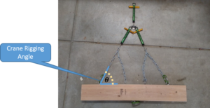
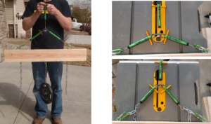
This demonstration depicts the importance of rigging angles during crane lift operations on a construction site. Reducing rigging angles results in a significant amplification of forces in the rigging, potentially leading to failure. By varying the connection points and sling length, students will be able to calculate the predicted forces and analyze the best combination of connection points and sling lengths to successfully complete the critical lift. The demonstration should take 15-20 minutes.
Engineering Principle
A sling’s working load limit (WLL) is based on a crane lift performed at a straight (90°) angle. The forces in rigging (sling, chain, wire rope, webbing, shackles, etc.) increase substantially as the angle formed by the sling leg and the horizontal becomes smaller. The following chart shows the increased force applied to the rigging when the rigging angle is reduced. The key engineering principle with this demonstration is related to an understanding of statics. Students must comprehend that decreasing the angle creates a horizontal force component that in turn increases the tension in the rigging. This can be derived using the figure below.
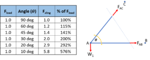


While increasing the connection angle of a two-point lift may be required to increase the stability of the lift, careful consideration must be taken in regards to the sling capacity and weight of the lift.
What You Need
| Item | Quantity | Description/Clarification |
|---|---|---|
|
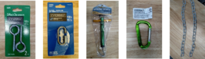
3/16 in Chain |
(2) 2 ft sections |
These represent the sling for the lift. |
|
Twist Link Chain |
1 ft |
This is smaller than the straight chain and is used to connect the weight plate to the spring link on the lower screw eye. |
|
2×6 x 3 feet |
1 |
Most pieces come in 8 foot sections. Once cut to size, this is the critical lift. |
|
3/4 in x 3 in Screw Eyes |
7 |
These are used for the rigging connection points on top and the load connection point on the bottom. 130-pound capacity. |
|
3/16 in quick link |
1 |
This locks and holds the two spring scales along each chain. It also is used for the top spring scale to analyze the total weight of the lift. 450-pound capacity. |
|
3 in spring link |
3 |
These are used for quick connections of the chains to the screw eyes and the weight to the load screw eye. 150-pound capacity. |
|
20-lb spring scale |
3 |
These scales measure the weight of the lift and along each chain. |
|
10-lb weight plate |
1 |
This increases the weight of the critical lift. |
How It’s Done
Before Class: Build and verify your model. The imperfect connections at the screw eyes and the variation in the spring scale as a load is applied make predicting the exact angle difficult. The placement of the screw eyes and the length of the chain are intended to replicate scenarios with the connections at 30°, 45°, and 60°.

After cutting the 2×6 to 3ft. length, install the screw eyes along the centerline at the distances shown above. To ensure the spring scale hook remains centered during the lift (and creates an equal force in both scales), use wire or duct tape to prevent its movement. Display the 2×6 at the front of the class, but do not have anything connected to it. Let the students build their answer as they work to solve the problem.
In Class: The scenario is as follows; the students are new project engineers on a job site. The project manager is out sick and leaves them in charge for the day. The easy day gets complicated when the crane operator insists on executing the project’s critical crane lift on short notice due to impending weather. However, due to the unscheduled nature of the request, the project engineer is unsure if the slings on hand are capable of safely executing the lift. The project engineer tells the crew that the crane lift will happen in 15 minutes, which buys some time. The project engineer runs back to the trailer to calculate how to use the two (2) 11-ton slings to lift the 15 to 16-ton object worth $2 million. The object has only three “picking eyes” on each side to maintain its balance. The crane operator recommended the connections farthest from the center to help with stability.

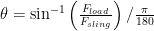
Theory: Given the fixed connection options, have the students calculate the tensile forces in the sling using the farthest connection (12 inches from center). Ask them what angle they would recommend if they didn’t have time for calculations, and why? By adjusting the basic equation to
Example: The total weight of the demonstration should be 15-16 pounds. Explain to the students that they could use trigonometry to calculate the required sling lengths given the fixed connection points and desired connection angles. However, the variation in this model makes it difficult to perfectly replicate such detailed specifics. As the spring scales extend to register the weight, they alter the length of the cable and therefore the angle at the connection and the resulting tension within the cable. Calculations that include spring deflection yield the following cable length approximations to get the desired connection angles: 30° (no chain, but chain must hang from connection for consistent weight), 45° (3 links), and 60° (9 links). These numbers only apply when analyzing the connection that is 12 inches from center. Ask for four volunteers (1 on each side of the lift, 1 to make the connections and document the results, and 1 to hold the top scale when the lift is tested). Test the model at the approximate angle the students chose as the way they would conduct the lift. Then, conduct the connections described above for 30°, 45°, and 60°. Lastly, ask the students to create the worst-case scenario for the rigging and test that example as well. By keeping the lift symmetrical, the weight of the lift can be divided by two and analysis conducted on half of the rigging that creates a right triangle. Given 


The following chart compares theoretical angles based on perfect trigonometry to the test angles calculated from the resultant forces under varying load connections.
 |
Expected Angle ( ) ) |
|
|
Test Angle () |
|---|---|---|---|---|
|
No chains |
30.0 deg |
15.0 |
7.5 |
30.0 deg |
|
3 links |
45.0 deg |
11.8 |
7.5 |
39.5 deg |
|
9 links |
60.0 deg |
9.0 |
7.5 |
56.4 deg |
As shown above, the angles are not always perfect matches, but are close enough to effectively highlight the amplification of forces in the sling based on rigging angles. Notice the applied force on the sling exceeds its 11lb capacity at 45 degrees!
Finally, ask the students if they have ever heard of the American Death Triangle. If a student has, have them explain its meaning to the class. This refers to a common source of fatalities in rock climbing and the principles are quite similar to equipment rigging.
Additional Application:
This makes for a good discussion on Factors of Safety. Ask the students about their tolerance for safety and how close to the sling’s capacity would they execute the lift. Did they inspect the slings? The sling’s rating is accurate when it leaves the manufacturer, but how have they been maintained? Are they rusty, worn, or frayed?
It is entirely possible that a foreman or superintendent does not recognize the implications of different rigging angles. Focus on emphasizing the importance of being able to say “No” to unexpected job site suggestions as a young engineer. Safety should drive the schedule.
This gives an opportunity to discuss other rigging arrangements such as the use of a spreader bar.
Talk about real world examples where critical lifts did not go as planned and discuss the serious implications about the failures. This is a great time to include a PowerPoint slideshow with pictures of failed crane lifts.
It was interesting when you talked about how rigging forces increase substantially the smaller the horizontal angle with the sling leg becomes. My uncle is interested in working with a truck system provider since he needs a custom crane for his project this summer. I’ll share this info for peace of mind about his safety while working with the crane truck.